
Tooling
This mode is used to edit the tooling (punches and dies) being used in a model. As you perform any editing operation on the model, collision checks are performed and the bend navigator display on the top is updated. If there are any potential collisions or other issues with the tooling setup, they are indicated by red squares and touching them reveals more information.
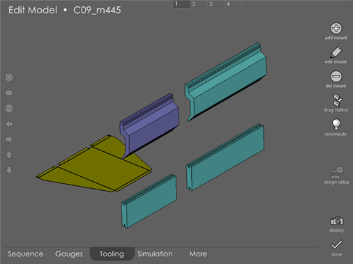
Menu options
Direct manipulation of parts and tooling
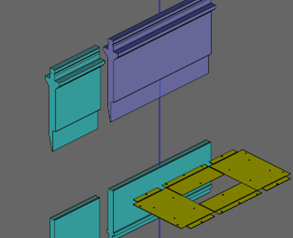
Touch a tool and drag it along the rail direction to re-position the tool on the rail. As you do this, snap guidelines are drawn to help you precisely align the tool with other already-mounted tools. If you touch the tool near its centre when you start dragging it, then you can align the center of the tool with the center of another tool. See the below example where we are dragging the punch and aligning it precisely with the die:
Similarly, we can pick up a tool by touching near its left edge or right edge, and that edge can then be used for precise alignment. You can also touch the part near the bend line and drag it laterally along the machine axis to re-position the part to another tooling station. While dragging tools, you can pick up a part by the left, center or right edge of a bend line, and corresponding snap line displays are drawn to help positioning the part precisely.
add mount
The add mount button is used to add new tooling (a punch, die, punch holder or die holder). Tapping this brings up a panel where you can select a punch, a die, a punch holder or a die holder; then press d in this panel to add the tool.
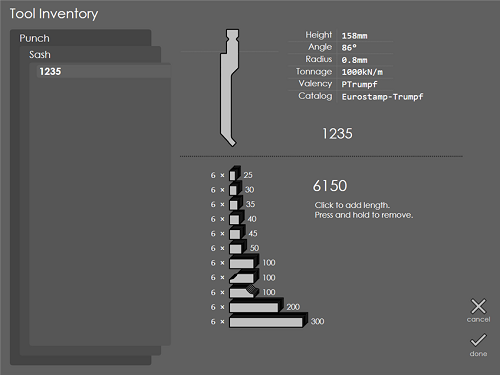
The tool is added with a length computed based on the current workpiece; you can subsequently edit the length or position of the tooling mount.
edit mount
Tap the edit mount to modify the length, position or other details of the currently selected tool mount (the one that is displayed in magenta). To edit a different mount, touch that first to select it, and then touch Edit Mount. The command displays a panel like the one below:
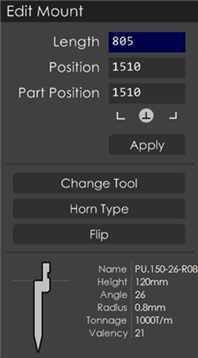
The Length setting can be used to modify the length of the tool mount; will compute the closest possible length to the one requested based on the tool pieces available in inventory.
The Position setting specifies the position of the tool on the machine. You can specify the left, center or right edge of the tool position by tapping one of the three alignment icons under the Part position input box.
The Part Position setting positions the currently selected bend line in the workpiece along the machine. For some bends, it is necessary to precisely position the part relative to the tool to avoid flanges from colliding into the punch; this setting allows fine controlling over the part position. Like the tool position, you can specify the part position by the left, center or the right end of the bend line by selecting one of the alignment icons.
The Apply button is used to apply the changes made to the Length, Position or the Part Position to the model. After you do this, will check for collisions, and if there are any, the Bend Navigator on the top of the screen will glow red, displaying the problems.
The Change Tool button is used to replace this tool with a different one, while keeping the mounting position and length identical (where possible). Touching this button brings up a tool selection panel like the one shown in the picture that follows.
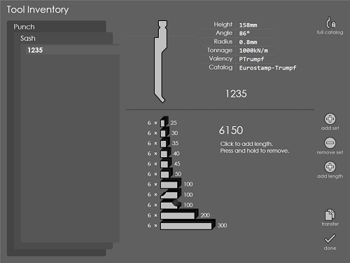
We are now replacing a punch with another punch.
Since the original punch is a Goose Neck punch, other goose neck punches that are suitable are displayed first. To switch to a different shape of punch, here you touch the Goose Neck label and pick another shape; then another punch is picked. An image of the selected punch and the details (height, angle) are shown. Once you have selected a suitable replacement tool, touch the done button to change the tool mounted in the station (a collision check will immediately be done to verify that the tool you have selected is acceptable).
The Horn Type button is used to switch between different shoulder (or horn) settings for the currently selected tool. This button appears only if you have a punch selected, and the punch has some shoulder segments in the inventory.
The image below shows the Horn Type button being used to cycle through different shoulder settings for a punch:
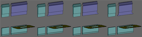
Use the Flip button to flip the mounted tool.
del mount
Use this to remove the currently selected tool from the setup.
Deleting a punch holder
When you delete a punch holder, checks if the punch underneath can be mounted directly on the punch rail. If this is the case, then the punch moves up and fixes on the rail. Otherwise the punch is also deleted. When you replace a punch holder with a different one, the punch underneath is shifted up or down appropriately to accommodate their difference in heights. If the new punch holder cannot hold this punch (valency different) then the punch is dropped.
drag station
A station is a punch and die mount, along with the parts that are processed there.
Use this button to re-position an entire station along the machine rail. Touching this button displays a Station Position dialog to type-in a value. The value that is displayed (and the one you type in) is the left edge of the punch mount. Once you press the OK mark on the dialog, the die and the part also get dragged along with the mount and remain aligned correctly with respect to each other. This operation is often used to drag an entire station off to one side so a new station can then be created using the Add Tool button.
recompute
Touching this button brings up the Select Tools dialog as shown in the picture below:
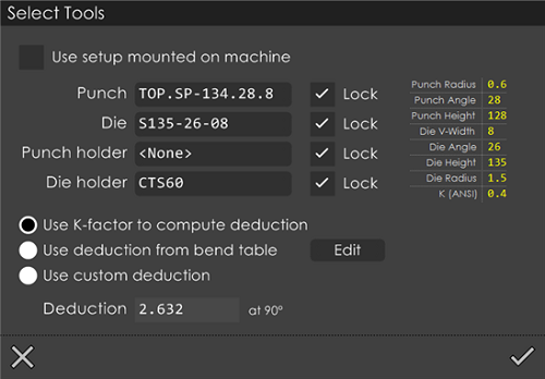
Using this tool selection dialog, you can select a different punch, turn some locks off to relax some constraints that you created using the Part Settings dialog during the create phase.
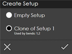
new setup
Clicking this displays the New Setup dialog (see picture below) that allows you to create a new setup for the current bend. This dialog also displays all the available setups, along with the list of bends that are currently using them
assign setup
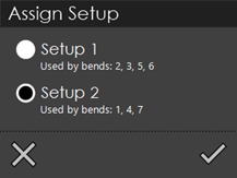
Clicking this displays the assign setup dialog (see picture below) that allows you to set the current bend to use a different setup. This dialog displays all the available setups, along with the list of bends that are currently using them. Use this dialog to switch all bends over to a single setup, and then do further adjustments to that setup (like changing some station lengths or re-positioning the part to a different station). After all the editing is done, save the model. At this point, any setups that are not used by any bends are discarded, and the program becomes a "single setup" program.
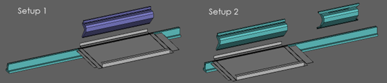
When a new setup is assigned to a bend, it tries to automatically shift the part position along the machine axis until moved under a suitable station. For example, see picture below for a before-and-after view of a setup change. When the setup was changed, the part got shifted to the left so it would correctly engage with the punch and die of the first station on the left.
If no suitable stations are found (for example, all of them are too short, or all of them collide) then the part position is unchanged, and you can drag the part into a new position manually.