RightAngle Reference Manual

  • Welcome to RightAngle Control
  • Introduction
    • User Interface
    • Gauging
    • Tools
    • General panels
    • Application notes
      • Selection of Tools
      • Air bending
      • Large Radius Bending
      • Hemming
      • Coining
  • Home
  • Create
    • From Profile
      • Profile Selection
      • Create/Edit a Profile
      • Extrude
    • Fold Flat DXF
      • Main Screen
      • Create
      • Edit
      • Fold
    • Import 3D model
      • Main screen
      • Unfold
      • Do Tooling
    • Direct Programming
      • Main Screen
      • Add/Remove
      • Settings
      • Run
      • Navigate Bend
      • Corrections
      • Jog
      • Table Programming
    • Setting page
    • Create Tool
  • Edit
    • Sequence
    • Back gauges
    • Tooling
    • Simulation
  • Run
    • Main Screen
    • Model Based WF
      • Setup Sheet
      • Run Program
    • Program Based WF
      • Info Screen
      • Run
    • Corrections
    • Edit Cycle
  • Settings
    • Jog Axes
    • Manual Program
    • Tool Inventory
    • Other Settings
  • Feature list
    • Angle Measurement System (Pre-release)
      • IRIS Plus (Pre-release)
  • Tandem Operation
    • Operation
    • Communication Error
  • Impressum
  • FAQs
    • Licensing
Run
/
Model Based WF
/
Run Program

Run Program

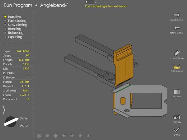
In this environment, the press-brake is being used to perform the bending. Each bend essentially consists of two phases:

  1. Tap the foot pedal to move the back-gauges into position.

  2. The sheet is positioned into the brake, and press and hold the foot pedal to perform the bend.
runprog

The indicators on the top left guide you through this cycle.

The 3D display on the right displays how the blank should be inserted into the machine for each step. As you go through the operations, this picture changes to display the appropriate bend. Since this is a live 3D view, you can use the display button to change what is displayed, or to change the viewpoint. You can also use the zoom and pan navigation buttons along the bottom of the screen to manipulate the 3D view.

Part Count

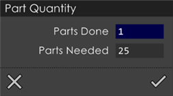
The part quantity is displayed to the left along with the other details displayed about the program being processed. This counts as the parts are being processed. To set the current part count, or to set a maximum quantity, just tap on the part count number. This brings up an input box like the one below:
partqnt

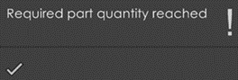
This allows you to set both the current part count and the maximum(optionally). Leave them blank, if you don’t have a pre-set maximum you want to stop at. If you do set it, and that quantity is reached, the following alert message is displayed:
qnt

Contents

  • Part Count
Setup Sheet Program Based WF

      Copyright © 2025 TRUMPF Metamation. All rights reserved.

    Compiled by Bento