RightAngle Reference Manual

  • Welcome to RightAngle Control
  • Introduction
    • User Interface
    • Gauging
    • Tools
    • General panels
    • Application notes
      • Selection of Tools
      • Air bending
      • Large Radius Bending
      • Hemming
      • Coining
  • Home
  • Create
    • From Profile
      • Profile Selection
      • Create/Edit a Profile
      • Extrude
    • Fold Flat DXF
      • Main Screen
      • Create
      • Edit
      • Fold
    • Import 3D model
      • Main screen
      • Unfold
      • Do Tooling
    • Direct Programming
      • Main Screen
      • Add/Remove
      • Settings
      • Run
      • Navigate Bend
      • Corrections
      • Jog
      • Table Programming
    • Setting page
    • Create Tool
  • Edit
    • Sequence
    • Back gauges
    • Tooling
    • Simulation
  • Run
    • Main Screen
    • Model Based WF
      • Setup Sheet
      • Run Program
    • Program Based WF
      • Info Screen
      • Run
    • Corrections
    • Edit Cycle
  • Settings
    • Jog Axes
    • Manual Program
    • Tool Inventory
    • Other Settings
  • Feature list
    • Angle Measurement System (Pre-release)
      • IRIS Plus (Pre-release)
  • Tandem Operation
    • Operation
    • Communication Error
  • Impressum
  • FAQs
    • Licensing
Introduction
/
Gauging

Gauging

When using a press brake to bend parts, it is important to position the material correctly. The back gauge helps by holding the part steady and ensuring it is in the right place before bending. It guides the machine to the exact spot where the bend should be made.

In RightAngle Control, you’ll see settings like X, X1, X2, Z1, Z2, R, R1, and R2. These are just labels for how the back gauges move to help position the part correctly before bending.
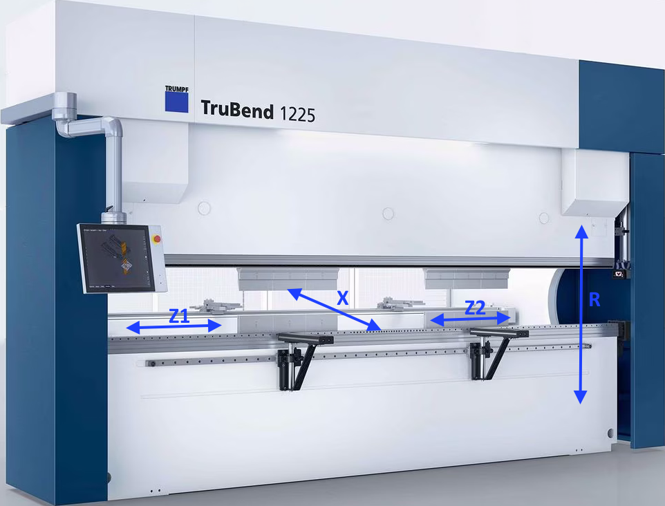
axis

Here is a simple breakdown:

X-Axis: Front to Back

  • X, X1 and X2 control how far the gauge fingers move into the machine, basically determines how deep the sheet goes.

  • On some machines, you can move the left and right gauges separately (that’s what X1 and X2 are for).

  • This controls how far your bend line is from the edge of the part.

Z-Axis: Side to Side

  • Z1 and Z2 move the gauge fingers left and right across the table.

  • Z1 is usually the left finger, and Z2 is the right finger.

  • This helps you create angled bends or position longer parts more accurately.

R-Axis: Up and Down

  • R, R1 and R2 adjust the height of the back gauge fingers.

  • This is helpful if your part has flanges or bends that stick up, as you can lift the fingers out of the way or support different part heights.

User Interface Tools

      Copyright © 2025 TRUMPF Metamation. All rights reserved.

    Compiled by Bento