IRIS Plus (Pre-release)
The Lazer Safe® IRIS Plus is a real-time optical angle measurement and correction system integrated into the press brake’s safety photocells. It uses a laser transmitter and a high-speed camera receiver to measure and correct bend angles during the bending process.
Core capabilities
- Real-Time Measurement
-
The camera captures live frames of the bending profile, measuring the angle and calculating spring-back in real time.
- Active Angle Correction
-
The system sends measurement data directly to the CNC controller, enabling instantaneous depth adjustments to match the programmed angle.
- Non-Contact Technology
-
The system uses optical image analysis instead of physical contact with the sheet metal. This prevents surface marks, eliminates collision risks, and does not restrict operator movement.
- High Precision
-
Measures angles with accuracy better than 0.1° (depending on setup), reducing scrapped parts and the need for test bends.
Operational specifications
| Specification | Details |
|---|---|
Die compatibility |
V-openings from 8 mm to 35 mm |
Material thickness |
1 mm to 4 mm |
Workspace size |
Optimized for small to medium press brakes. Measurement accuracy may decrease on parts longer than approximately 2.5 m due to light refraction. |
Enable IRIS Plus in RightAngle
-
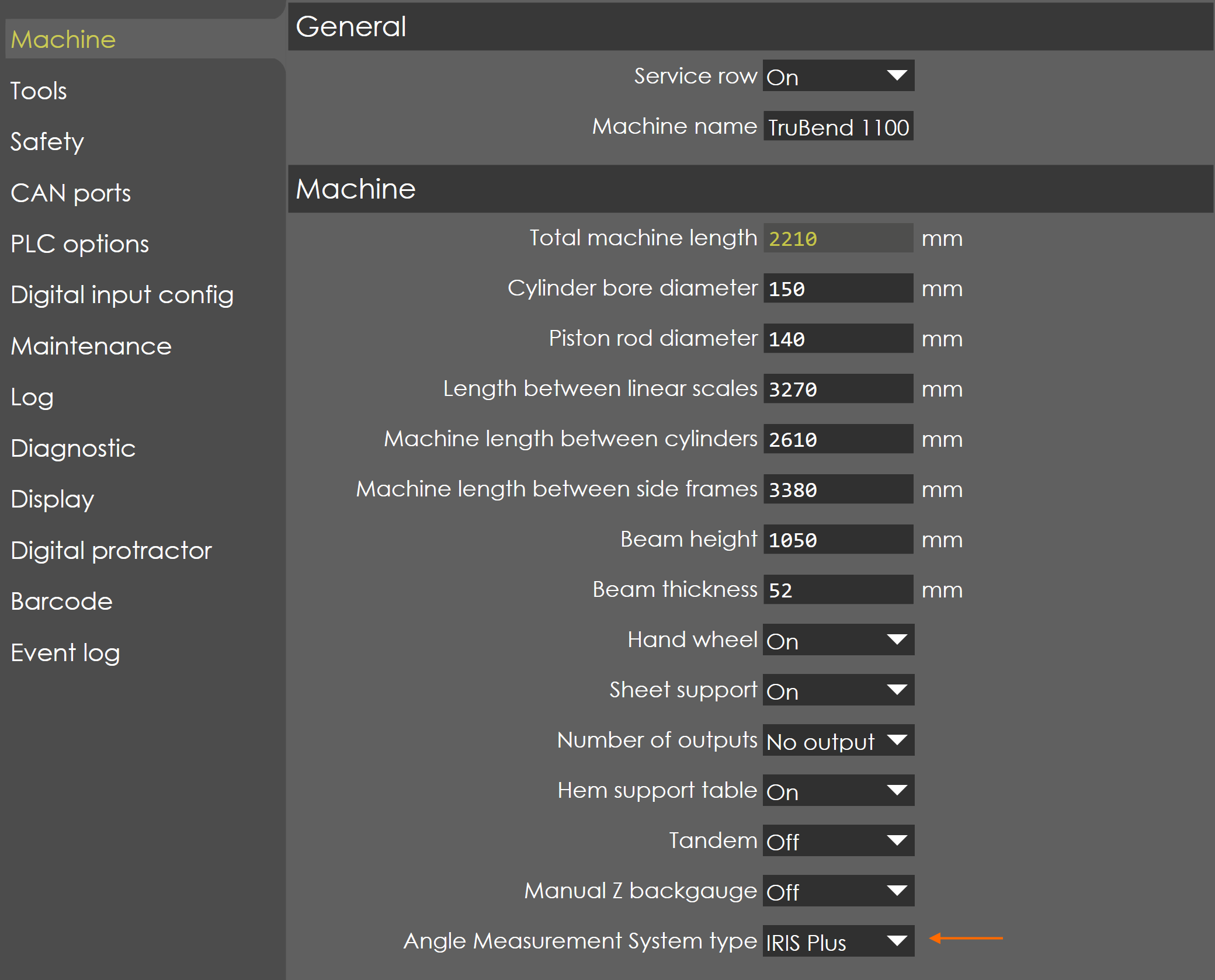
Navigate to Settings → Other Settings → Machine Settings and set the user level to Service.
-
In General Parameters, click the Machine tab.
-
In the Machine section, set the Angle Measurement System type to IRIS Plus.
Configure IRIS Plus parameters
When IRIS Plus is enabled, two configuration areas become available:
-
AMS tab — Located in Machine Settings → General Parameters.
-
Angle Measurement defaults — Located in Machine Settings → Defaults.
General parameters
Open the AMS tab in General Parameters to view or edit the following settings:
| Parameter | Range | Description |
|---|---|---|
Angle Difference for SB Measure |
1° - 30° (default: 10°) |
The offset added to the target angle to calculate the initial spring-back measurement angle. |
Reduce Pump Speed in Decompression |
0 - 1500 RPM |
Reduces pump speed during decompression when AMS is active. Applies only when the pressure valve is configured as a servo motor. |
Reduce Decompression Gain Factor |
1 - 100% |
Reduces the gains used during decompression. |
Angle Stability Delay Time |
0 - 10000 ms |
Delay before capturing a stable angle reading from the sensor. |
SpringBack Check Delay Time |
0 - 10000 ms |
Delay before checking the angle change during spring-back measurement. |
IRIS Plus communication settings
Configure the following network settings to establish communication with the IRIS Plus sensor:
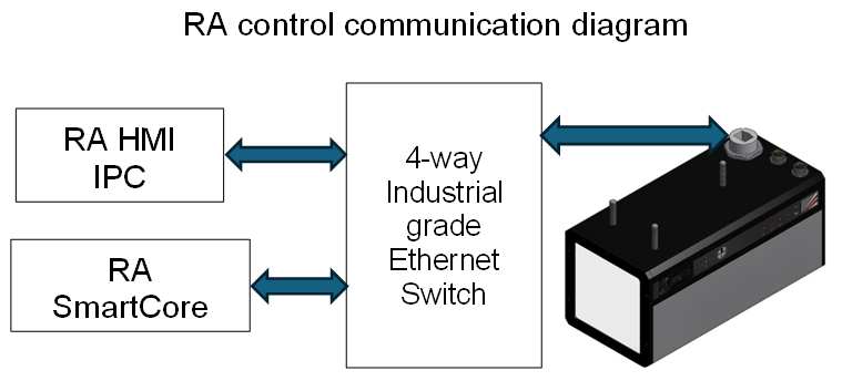
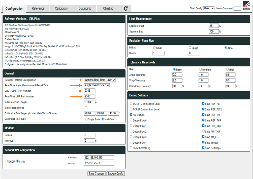
 - Use Ethernet CAT6 straight cable for all the interfaces and define the IP address such that they are all in the same network.
| Parameter | Default value | Description |
|---|---|---|
IP Address |
192.168.100.110 |
Network address of the IRIS Plus device. |
TCP Port Number |
2345 |
Used for reference and calibration processes. TCP is not used for real-time streaming because it requires acknowledgment for each transmission. |
UDP Port Number |
2346 |
Used for real-time angle data streaming. On the IRIS Plus web page, set the Network Protocol Configuration to Generic Real Time (UDP) and the Real-Time Angle Measurement Type to Angle Result Type 3. |
The available angle result types are:
-
Angle Result Type 1 — Basic output: expected angle, measured angle, warp, quality indicator, and tolerance flags.
-
Angle Result Type 2 — Includes measured values with tolerance acceptance status.
-
Angle Result Type 3 — Detailed measurements, quality indicators, and machine data for in-depth analysis. (Recommended)
Tolerance settings
Navigate to Default Settings → Bend Program → Angle measure to configure angle tolerances:
| Parameter | Range | Description |
|---|---|---|
Warning tolerance |
0.1° - 2° (default: ±0.5°) |
If the measured angle deviates from the target by more than this value, a warning is displayed. |
Error tolerance |
0.1° - 5° (default: ±1°) |
If the measured angle deviates from the target by more than this value, an error is displayed. |
| Both tolerances can also be adjusted for a specific bend in the Corrections → Angle Measurement tab. |
Default mode for programs
On the same page, the AMS setting controls how Default mode for 3D program are assigned to bends in 2D and 3D programs:
| Mode | Description |
|---|---|
None |
All bends are set to "None" with no reference. Assign Identify or Learned mode to each bend manually. |
Auto |
AMS modes and references are assigned automatically for all bends. |
| When set to Auto, some bends may still display as "None". Verify and adjust modes as needed. |
Calibration
Calibration ensures accurate angle measurement. Perform calibration when the IRIS Plus sensor is selected.
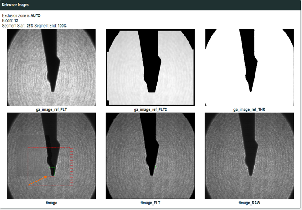
Reference image
A reference image captures the exact position of the punch tool tip. It is recommended to capture a new reference image at least once a week.
Calibration procedure
-
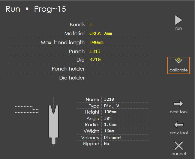
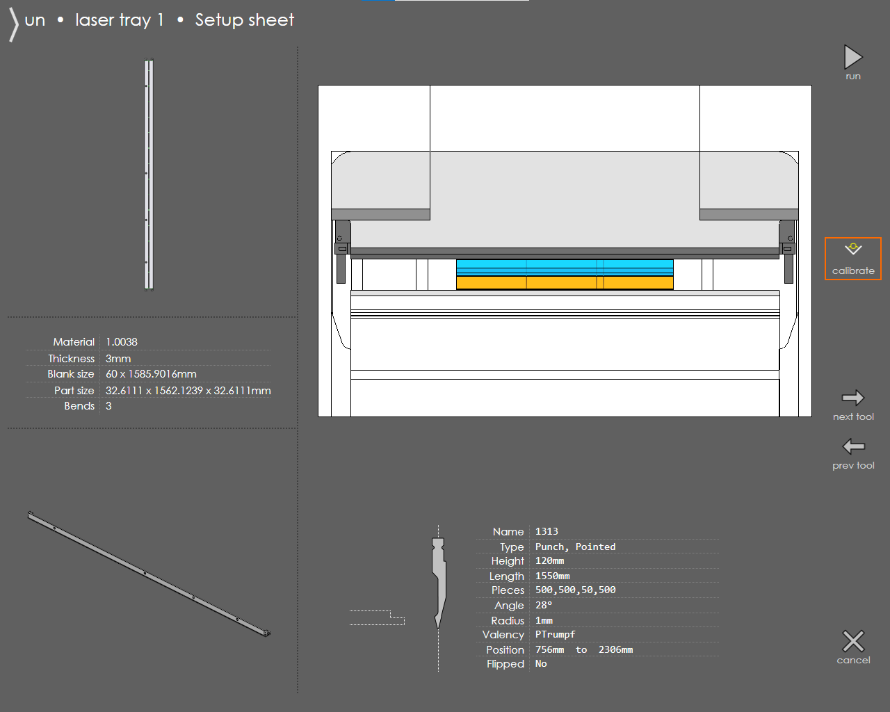
Run a program and navigate to the setup sheet. The Calibrate button is available for IRIS Plus AMS.
-
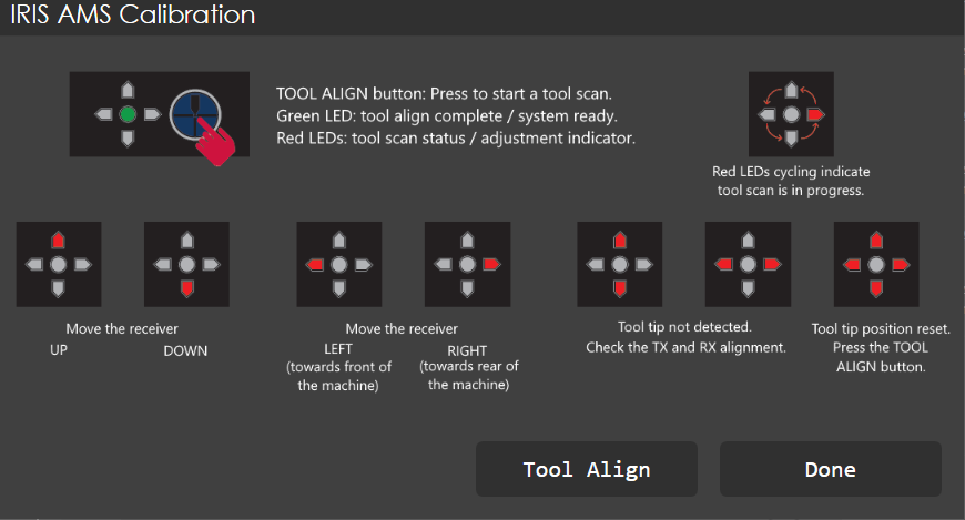
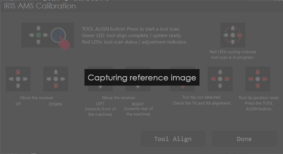
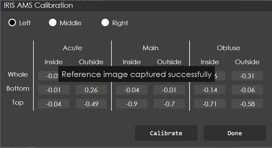
On the IRIS AMS calibration page, click Tool Align. The AMS captures a reference image and displays a confirmation message.
-
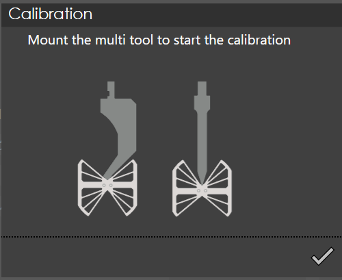
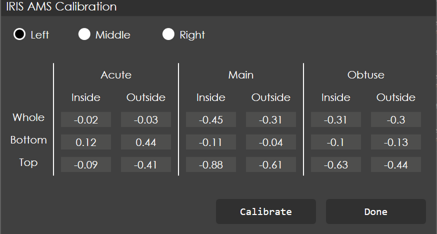
Mount the suggested calibration tool on the machine and click Done. The calibration page displays three options: Left, Middle, and Right.
-
Select the side where the calibration tool is placed and click Calibrate. Repeat for all three sides.
-
The calibrated values (Acute, Main, and Obtuse) are updated on the page.
-
After completing all three sides, click Done.
The calibration tool type depends on the punch shape:
-
Triple-angle side — Use with Straight or Pointed punches.
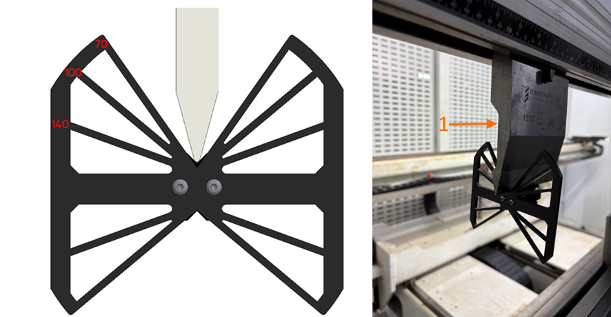
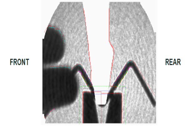
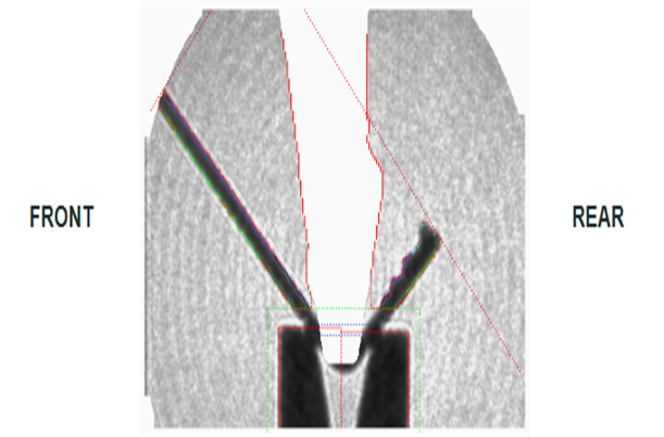
① Pointed punch
-
Double-angle side — Use with Gooseneck punches.
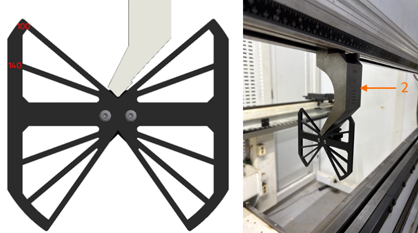
② Gooseneck punch
AMS modes
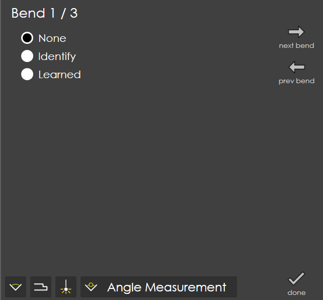
AMS operates in three modes:
None
AMS is inactive. No angle measurement or correction is performed.
Identify
In Identify mode, AMS measures the spring-back and calculates corrections automatically:
-
AMS bends to the initial angle (target angle + SB measure angle).
-
During decompression, it calculates the spring-back and determines the correction.
-
It applies the correction to achieve the target angle.
-
The correction values are stored for use by subsequent bends in Learned mode.
Bending sequence: Fast Closing → Slow Closing → SpringBack Measure → Decompression → Pressing → Decompression → Opening
Before BDC settings
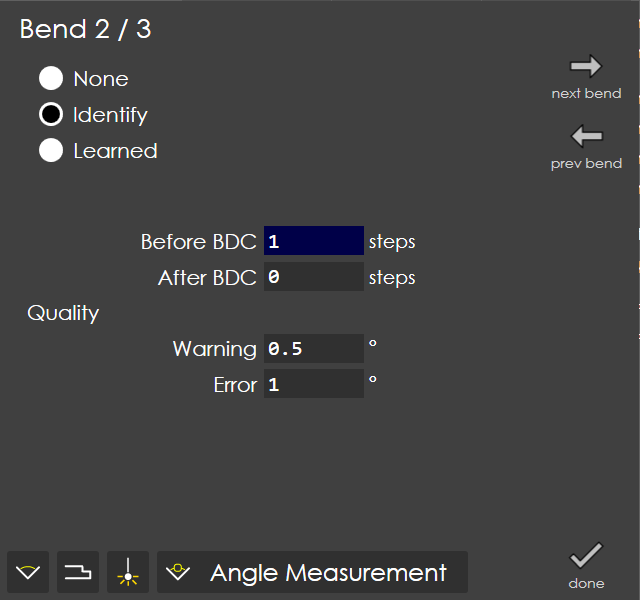
| Setting (Range: 1 to 2) | Description |
|---|---|
Before BDC = 1 |
AMS bends to the initial angle (Target angle + SB measure angle), then decompresses to calculate spring-back and corrections. On the next pressing, AMS moves to the LDP point targeting: Target angle - SpringBack value.
Bending sequence: Fast Closing → Slow Closing → SpringBack Measure → Decompression → Depends on "After BDC" setting |
Before BDC = 2 |
AMS bends to the initial angle (Target angle + SB measure angle), then decompresses to calculate spring-back and corrections. On the next pressing, AMS reaches the target angle, stops, and decompresses to recalculate spring-back. For subsequent pressings, AMS moves to the LDP point targeting: Target angle - recalculated SpringBack value.
Bending sequence: Fast Closing → Slow Closing → SpringBack Measure → Decompression → SpringBack Measure 2 → Decompression → Depends on "After BDC" setting |
After BDC settings
| Setting (Range: 0 to 1) | Description |
|---|---|
After BDC = 0 |
AMS measures the final angle after decompression, then proceeds to the opening state. No corrections are applied. |
After BDC = 1 |
AMS measures the final angle after decompression. If corrections are still required, AMS re-presses to the same LDP point. |
Learned
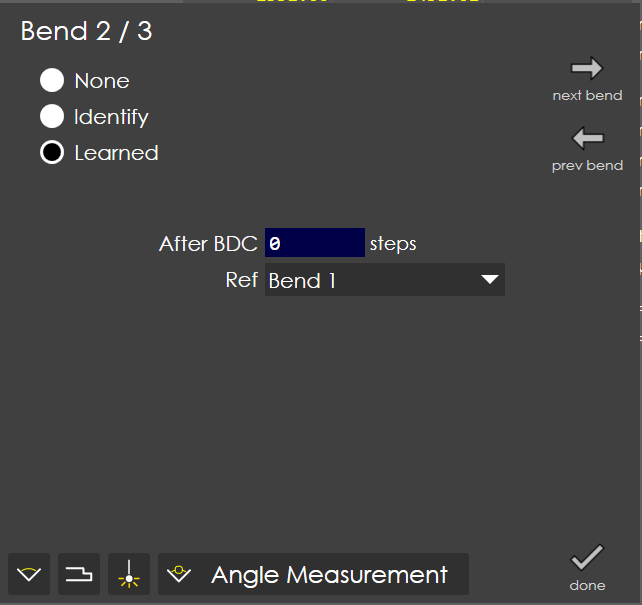
In Learned mode, AMS uses the correction values obtained from a previous Identify bend as a reference:
| Setting (Range: 0 to 1) | Description |
|---|---|
After BDC = 0 |
Correction values from the Identify bend are applied. AMS measures the final angle after decompression, then proceeds to the opening state. |
After BDC = 1 |
Correction values from the Identify bend are applied. AMS measures the final angle after decompression. If corrections are still required, AMS re-presses to the same LDP point. This compensates for differences in sheet thickness. |
|
Setting the reference bend
Select a bend from which Identify mode corrections were obtained. Only bends with the same target angle should be used as a reference.
|
Set up AMS for a bending program
The AMS workflow is the same for 2D, 3D, and Direct programs. The following example uses a two-bend Direct program:
-
Set the AMS mode for both bends.
-
On the Run page, click Correction → Angle Measurement to open the mode selection page.
-
Set the first bend to Identify and the second bend to Learned, with the reference set to Bend 1.
In 2D and 3D programs with Default mode for 3D program set to Auto, modes are assigned automatically. -
Start the bending process. After the first bend completes in Identify mode, the angle correction and spring-back values are displayed in the Angle field on the Run page.
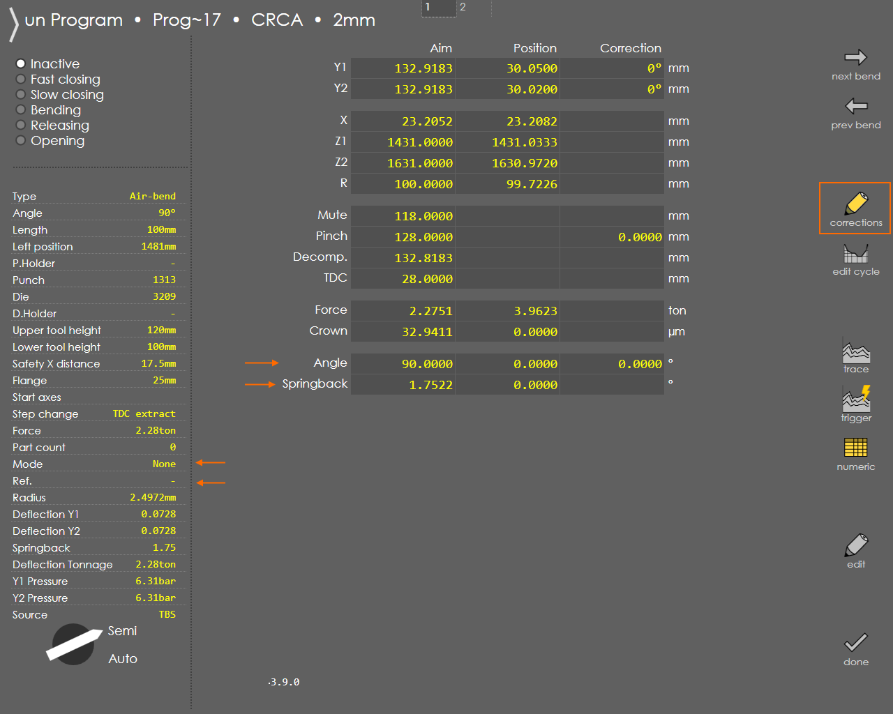
-
The correction values from the first bend are applied to the second bend automatically. The final angle is displayed after the second bend completes.
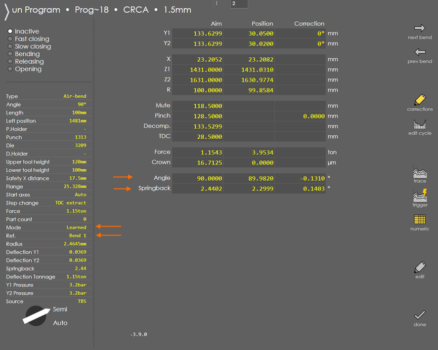
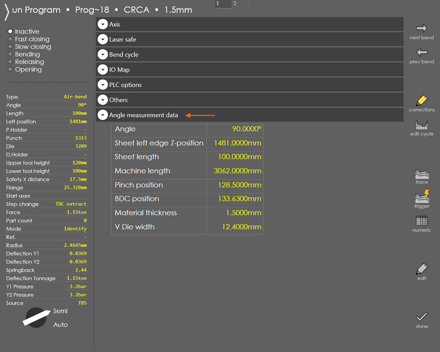
To view detailed angle measurement data:
-
Navigate to Settings → Other Settings → Machine Settings → General Parameters → Log → Diagnostics.
-
Enable Show IO Screen and save.
-
On the Run page, click Numeric and expand Angle Measurement Data.
Troubleshooting
The following table lists common AMS error messages and their causes:
| Error message | Cause and resolution |
|---|---|
Machine not referenced |
The machine has not been homed. Home the machine before attempting to take a reference. |
Failed to capture reference image |
A disturbance occurred near the tool during reference capture. Ensure the area around the tool is clear and try again. |
Release E-stop, press reset and try again |
The Emergency Stop is active. Release the E-stop, press Reset, and retry. |
Failed to calibrate, check whether multi-tool is mounted at punch tip |
The calibration side selected on the IRIS AMS calibration page does not match the side where the calibration tool is mounted. Select the correct side and retry. |
AMS - backgauge retraction required to avoid interruption |
The flange height is less than 50 mm and the backgauge is within the IRIS sensor range. Add a backgauge retraction to avoid interfering with the measurement. |
AMS not able to measure the angle, so manually measure it |
Angle measurement is not possible under the current conditions, but the result is within tolerance. This also appears when bending without a part. Measure the angle manually. |
IRIS - Received data not valid, check for any interruption |
An interruption occurred during bending. Check for obstructions or disturbances and retry. |
AMS - wrap angle exceeds, check sheet flatness or redo ref & calib |
The sheet may have burrs or uneven surfaces preventing accurate measurement. Check sheet flatness, and redo the reference and calibration if needed. |
Angle deviation greater than [warning tolerance] |
The measured angle deviates from the target by more than the warning tolerance (e.g., ±0.5°). Displayed in dull red. Review the bend and adjust if necessary. |
Angle deviation greater than [error tolerance] |
The measured angle deviates from the target by more than the error tolerance (e.g., ±0.8°). Displayed in bright red. Stop production and investigate the cause. |