
FL1
To enable FL1 axis in Axis Parameter, turn ON Regrip stations in General Parameters → Machine.
General
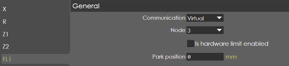
Communication
Range |
CAN / EtherCAT / Analog / Virtual / Smart axis |
Default |
Virtual |
Units |
|
Access |
Administrator |
Function
This parameter defines the type of communication between controller and drives.
Description
The controller supports five types of communication namely Analog Axis, Smart Axis, CAN Axis EtherCAT Axis and Virtual Axis.
Analog Axis: The Analog axes card is in-built in the controller and supports maximum of 4 analog axis, out of which first 2 axis are internally configured for Y1 & Y2 axis (RAM) and other 2 axis can be configured for backgauge or handwheel here.
Smart Axis: The Smart axes module is an indigenous axes control card which controls maximum of 4 axis. The communication between the controller and smart axes module is through a CAN protocol, but still the control type of Smart axes module is analog voltage.
CAN Axis: Many servo drives supports digital communication and one of such is called CAN interface. The communication between the controller and servo drives is CAN protocol , through which the data’s such as position command, velocity command etc., are digitally transferred. The main advantages of digital drives are accurate positioning, faster speeds, less cabling and etc. The controller can support maximum of 14 axes, excluding Y1 & Y2 axis.
EtherCAT Axis: Similar to CAN interface, EtherCAT is one of the faster growing communication protocol and almost all the servo drives supports this interface. The controller can support maximum of 14 axes, excluding Y1 & Y2 axis.
Virtual Axis: To deactivate the physical output of a configured axis, the Virtual axis selection is used. In this way, the mechanical movement of a configured axis can be deactivated but still the control shows the display of the axis, which are generated virtually. The controller can support maximum of 14 axes, excluding Y1 & Y2 axis.
Node
Range |
1 - 28 |
Default |
1 |
Units |
|
Access |
Administrator |
Function
This parameter defines the address of the configured axis.
Description
In order to identify the configured axis, each axis are denoted with node ID called address of the axis. The node ID needs to be specified in each of the drives, if the axes are configured as digital axis (CAN or EtherCAT). In this way, the controller can identify the axis and transmit the correct data to the particular axis.
| Make sure the axis name and node ID are configured correctly, else the mismatch can lead to wrong data transfer and accidents may occur. |
Hardware limit enabled
Range |
Checked or unchecked |
Default |
Unchecked |
Units |
|
Access |
Administrator |
Function
This parameter enables/disables the hardware limit switch function of axis.
Description
When this parameter is activated, if the axis crosses either positive or negative limit switch, it is stopped with emergency braking deceleration parameter. Depends on the type of the axis configured, the limit switches are connected to digital drives or smart axis module or analog control card.
| If either of any one limit switch is connected to the axis end limit input, then the other input must be connected to +24V or 0V depending on the connected module. |
Park position
| This option is available only for FL1 and FR1 axes. |
Limit

Maximum
Range |
-10000 to 10000 |
Default |
varies depends on the axis name |
Units |
mm |
Access |
Administrator |
Function
This parameter defines the maximum position the axis can be moved to.
Description
This value is used as a positive software limit. If a programmed or computed axis value is greater than this parameter, the value is limited at the maximum value and an error message appears on the screen.
X-Axis - Target > Positive software Limit
Minimum
Range |
-10000 to 10000 |
Default |
varies depends on the axis name |
Units |
mm |
Access |
Administrator |
Function
This parameter defines the minimum position the axis can be moved to.
Description
This value is used as a negative software limit. If a programmed or computed axis value is smaller than minimum, the value is limited at the minimum value and an error message appears on the screen.
X-Axis - Target < Negative software Limit
Speed and acceleration
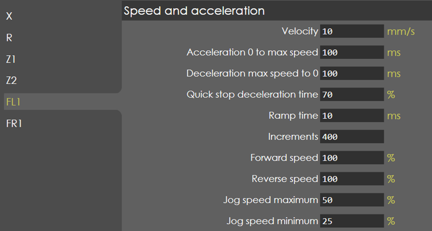
Velocity
Range |
-10000 to 10000 |
Default |
varies depends on the axis name |
Units |
mm/s |
Access |
Administrator |
Function
This parameter defines the maximum travel speed of the axis.
Description
Normally this value should be programmed to the maximum possible speed of the axis, when the control signal is at maximum.
Acceleration 0 to max speed
Range |
1 to 99999 |
Default |
125 |
Units |
ms |
Access |
Administrator |
Function
This parameter defines the acceleration time of axis.
Description
This is the nominal acceleration of the axis, used to control the axis from zero to maximum speed. This parameter must be programmed as the time in which the axis accelerates from zero to maximum speed.
Deceleration max speed to 0
Range |
1 to 99999 |
Default |
125 |
Units |
ms |
Access |
Administrator |
Function
This parameter defines the deceleration time of axis.
Description
This is the nominal deceleration of the axis, used to control the axis from maximum to zero speed when axis comes to its target position. This parameter must be programmed as the time in which the axis decelerates from maximum to zero speed.
Quick stop deceleration time
Range |
1 to 100 |
Default |
20 |
Units |
% |
Access |
Administrator |
Function
This parameter defines the Emergency deceleration time of axis.
Description
This is the quick stop deceleration of the axis, used to control the axis from maximum to zero speed during critical conditions such as hardware limit active, emergency stop active, etc. This parameter must be programmed as the percentage with respect to the deceleration time of the axis. For instance, if the deceleration time of axis is 100ms, then 20% of it corresponds to 20ms which is the quick stop deceleration time.
Ramp time
Range |
2-999999 |
Default |
10 |
Units |
ms |
Access |
Administrator |
Function
This parameter defines the ramp time called as Jerk of the axis.
Description
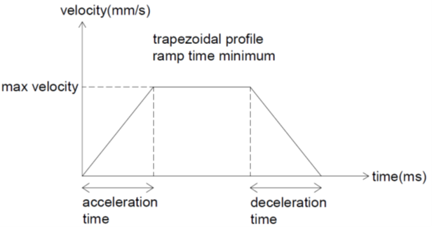
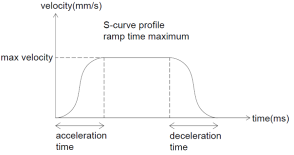
This is the time taken for the axis for the ramp up of acceleration and ramp down of deceleration. By this way, the trajectory profile of the axis can be varied from 'Trapezoidal' to required 'S-curve' profiles. Higher the ramp time value will have smooth acceleration and deceleration of the axis; lower values may create in-stability in the axis, such as vibration, overshoot etc.,
Increments
Range |
0-4294967296 |
Default |
1280000 |
Units |
|
Access |
Administrator |
Function
This parameter defines the number of increments of the axis.
Description
This parameter is the number of increments given by encoder per revolution of the motor. For Analog axis and Smart axis interface, if an incremental encoder is connected then the number of increments is 4 times multiplied by number of pulses. For instance, if a 2500 PPR encoder is connected, then the number of increments is 10000 (4 x 2500).
For digital interface of axis, the drive manufacturer specifies the number of increments of the encoder. For instance, Delta drives & motors - Increments: 1280000, Panasonic A6 drives & motors - Increments: 8388608, etc.
Forward speed
Range |
1 - 100 |
Default |
100 |
Units |
% |
Access |
Administrator |
Function
This parameter defines the maximum forward speed during program run mode.
Description
During program run mode, it is possible to control the forward speed of the axis from its maximum configured velocity. This parameter is defined in terms of percentage with respect to the maximum velocity of the axis.
Forward speed
Range |
1 - 100 |
Default |
100 |
Units |
% |
Access |
Administrator |
Function
This parameter defines the maximum reverse speed during program run mode.
Description
During program run mode, it is possible to control the reverse speed of the axis from its maximum configured velocity. This parameter is defined in terms of percentage with respect to the maximum velocity of the axis.
Jog speed maximum
Range |
1 - 100 |
Default |
50 |
Units |
% |
Access |
Administrator |
Function
This parameter defines the maximum speed in jog or manual mode.
Description
This parameter is defined in terms of percentage with reference to the maximum configured velocity of the axis. Also, this speed corresponds to the big plus and minus button available in jog mode page.
Jog speed minimum
Range |
1 - 100 |
Default |
25 |
Units |
% |
Access |
Administrator |
Function
This parameter defines the minimum speed in jog or manual mode.
Description
This parameter is defined in terms of percentage with reference to the maximum configured velocity of the axis. Also, this speed corresponds to the small plus and minus button available in jog mode page.
Home Parameter
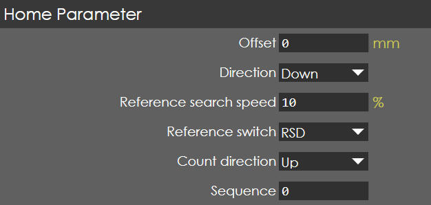
Offset
Range |
-10000 to 10000 |
Default |
518.17 |
Units |
mm |
Access |
Administrator |
Function
This parameter defines the reference offset position of the axis.
Description
With respect to this value, the axis position is displayed on the screen after the completion of reference cycle.
Direction
Range |
UP / DOWN |
Default |
UP |
Units |
|
Access |
Administrator |
Function
This parameter defines the direction of motion of axis during homing process.
Description
Generally, the homing will take place in the safe direction of the axis and in some cases, it may depend upon the location of the reference switch. The selection of direction 'UP', will move the axis in positive direction and that of 'DOWN' will move the axis in negative direction during homing process.
Reference search speed
Range |
1-100 |
Default |
50 |
Units |
|
Access |
Administrator |
Function
This parameter defines the speed of the axis during homing process.
Description
This parameter is defined in terms of percentage with respect to the maximum velocity of the axis. During homing process, the axis is moved with this speed in search of the reference cam.
Reference switch
Range |
RSD / EOT |
Default |
RSD |
Units |
|
Access |
Administrator |
Function
This parameter defines the type of reference switch used for the axis homing.
Description
The control supports 2 types of reference switch namely RSD (Reference Search Direction) and EOT (End Of Travel). When the homing command is activated, depending on the direction parameter, the axis starts to move towards the reference switch at a speed of reference velocity. After hitting the reference switch, the direction of axis movement is reversed and searches for the first reference pulse of the encoder and the homing process is completed.
| If EOT is selected and the axis is not homed, then the first hitting of the switch will not create any error message instead the direction of the axis changed. |
Count direction
Range |
Up/Down |
Default |
Up |
Units |
|
Access |
Administrator |
Function
This parameter defines encoder pulse counting direction.
Description
This parameter is used when the encoder pulse counting direction needs to be reversed.
Sequence
Range |
1-15 |
Default |
varies depending on axis |
Units |
|
Access |
Administrator |
Function
This parameter defines the homing sequence number of the axis. ==== Description
Generally, when the homing command is activated, all the backgauge axis will start to move in the homing direction. If the finger is near to the tools during homing, then the movement of the R - axis will make the finger to collide with tools. In order to avoid this type of collision, the sequence of homing will be very useful.
Typically, the X-axis will be homed first with Sequence number as 1 and other R & Z axis will be sequence number 2, to follow the homing process.
Control
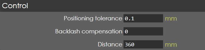
Positioning tolerance
Range |
0-10 |
Default |
0.1 |
Units |
mm |
Access |
Administrator |
Function
This parameter defines the maximum allowable position deviation of X axis.
Description
Generally, any axis will have certain position tolerance to set the 'in-position’output to the controller. It is with this output; the controller will go to next step in the bending cycle after the position of the axis. If the position is not reached within stipulated time, the controller will raise an error message in the screen:
X-axis - Position deviation exceeded
Backlash compensation
Range |
0-10 |
Default |
0 |
Units |
mm |
Access |
Administrator |
Function
This parameter defines the reversal compensation of the axis.
Description
Whenever there is a change in direction of motion, there may be some loss in the physical movement of the axis, which is called as Backlash. In order to avoid this loss, the control supports the backlash compensation. Generally, the “Ball screw & Nut”, “Rack & Pinion” mechanisms will have the backlash error, if properly measured and entered in this parameter will get the accurate positioning of the axis.
| The control have the limitation of this value to a maximum of 32767 increments. Still, the parameter accepts the value in 'mm', the controller internally interpolate it to number of increments. For instance, if the axis parameters are as follows: |
-
Increments - 128000
-
Distance - 10 mm
The maximum backlash value accepted here is 2.56mm (corresponds to 32767 increments).
Backlash compensation is set in order to eliminate backlash error in X axis.
Distance
Range |
0.001 to 10000 |
Default |
10 |
Units |
mm |
Access |
Administrator |
Function
This parameter defines the linear distance moved per revolution of axis motor.
Description
Generally, the rotation motion of axis motors are converted by linear motion using some driving techniques namely ball screw & nut, rack & pinion, etc., The conversion of rotary to linear motion displacement is entered this parameter in terms of millimetre (mm).
When an axis is driven by ball screw & nut mechanism, the pitch of the ball screw determines the linear displacement of the axis. For instance, when a 12mm pitch ball screw is used, then one rotation of motor will result in 12mm linear displacement and this value corresponds to 12.