Right Angle Reference Manual

  • Welcome to RightAngle Control
  • Introduction
    • User Interface
    • Gauging
    • Tools
    • General panels
    • Application notes
      • Selection of tools
      • Air bendig
      • Large radius bendig
      • Hemming
      • Coining
    • Design of bend parts
      • Min radius and flange length
      • Corner design
      • Bending tolerances
  • Create
    • From Profile
      • Profileselection
      • Create / edit a Profile
      • Extrude
    • Fold Flat DXF
      • Main screen
      • create
      • Edit
      • Fold
    • Import 3D model
      • Main screen
      • Unfold
      • Do Tooling
    • Direct Programming
      • Main screen
      • Add / Remove
      • Settings
      • Run
      • Navigate bend
      • Corrections
      • Jog
      • Table Programming
    • Setting page
    • Create Tool
  • Edit
    • Edit Sequence
    • Back gauges
    • Tooling
    • Simulation
  • Run
    • Main screen
    • Model based WF
      • Setup Sheet
      • Run Program
    • Program based WF
      • Info screen
      • Run
    • Corrections
    • Edit Cycle
  • Settings
    • Jog Axes
    • Manual Program
    • Tool Inventory
    • Other Settings
      • Machine Settings
      • General Parameters
        • Machine
        • Tools
        • Safety
        • CAN ports
        • PLC Options
        • Digital input configuration
        • Maintenance
        • Log
        • Diagnostics
        • Display
        • Digital Protractor
        • Barcode
      • Y-Axis Parameters
        • General
        • Mute
        • Feedback
        • Pressure Valve
        • Pressure Sensor
        • Idle
        • Fast Closing
        • Fast Closing Advanced
        • Pressing
        • Pressure Advanced
        • Decompression
        • Opening
        • Y-Axis Cold Condition Parameters
        • Crowning
        • Electric Press Brake
      • Axis Parameters
        • X Axis
        • Hand Wheel
        • FL1
      • Defaults
        • Bend Cycle
        • Bend program
        • Import/Export
        • Others
  • Tandem Operation
    • Operation
    • Communication Error
  • Impressum
Settings
/
Other Settings
/
Y-Axis Parameters
/
Mute

Mute

General

Mute

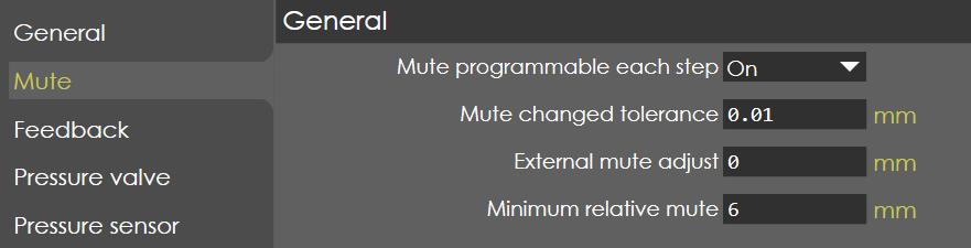
Mute programmable each step

Range

ON/OFF

Default

ON

Units

Access

Administrator

Function

This parameter enables/disables the editing of mute parameter for each bend in the program edit cycle.

Description

When this parameter is ON, the mute point can be changed for each individual bend of a program.

Mute changed tolerance

Range

0 - 9.99

Default

0.01

Units

mm

Access

Administrator

Function

This parameter defines a tolerance for the 'Mute changed' signal in the PLC.

Description

If there is a difference in the programmed and actual (from Laser safe) Mute point, a PLC flag is set within the RA software to signal the Mute has changed. If this signal is not necessary for small changes of Mute, a tolerance can be programmed with this parameter. If the difference between new and old Mute point is larger than this tolerance, the flag is set. This parameter is irrelevant if the flag is not used in PLC.

External mute adjust

Range

0-99

Default

0

Units

mm

Access

Administrator

Function

This parameter defines the mute distance additional to computed value.

Description

To program an alternative mute position intended to stop the beam at a higher mute position.

Minimum relative mute

Range

0-99

Default

6

Units

mm

Access

Administrator

Function

This parameter defines the minimum mute value of every V-die.

Description

The mute value that is programmed in the parameters of every V-die, is limited to this machine parameter value. The operator cannot program a value that is lesser than this parameter.

Contents

  • General
  • Mute programmable each step
  • Mute changed tolerance
  • External mute adjust
  • Minimum relative mute
General Feedback

      Copyright © 2025 by TRUMPF SE + Co.KG. All rights reserved.

    Compiled by Bento