Right Angle Reference Manual

  • Welcome to RightAngle Control
  • Introduction
    • User Interface
    • Gauging
    • Tools
    • General panels
    • Application notes
      • Selection of tools
      • Air bendig
      • Large radius bendig
      • Hemming
      • Coining
    • Design of bend parts
      • Min radius and flange length
      • Corner design
      • Bending tolerances
  • Create
    • From Profile
      • Profileselection
      • Create / edit a Profile
      • Extrude
    • Fold Flat DXF
      • Main screen
      • create
      • Edit
      • Fold
    • Import 3D model
      • Main screen
      • Unfold
      • Do Tooling
    • Direct Programming
      • Main screen
      • Add / Remove
      • Settings
      • Run
      • Navigate bend
      • Corrections
      • Jog
      • Table Programming
    • Setting page
    • Create Tool
  • Edit
    • Edit Sequence
    • Back gauges
    • Tooling
    • Simulation
  • Run
    • Main screen
    • Model based WF
      • Setup Sheet
      • Run Program
    • Program based WF
      • Info screen
      • Run
    • Corrections
    • Edit Cycle
  • Settings
    • Jog Axes
    • Manual Program
    • Tool Inventory
    • Other Settings
      • Machine Settings
      • General Parameters
        • Machine
        • Tools
        • Safety
        • CAN ports
        • PLC Options
        • Digital input configuration
        • Maintenance
        • Log
        • Diagnostics
        • Display
        • Digital Protractor
        • Barcode
      • Y-Axis Parameters
        • General
        • Mute
        • Feedback
        • Pressure Valve
        • Pressure Sensor
        • Idle
        • Fast Closing
        • Fast Closing Advanced
        • Pressing
        • Pressure Advanced
        • Decompression
        • Opening
        • Y-Axis Cold Condition Parameters
        • Crowning
        • Electric Press Brake
      • Axis Parameters
        • X Axis
        • Hand Wheel
        • FL1
      • Defaults
        • Bend Cycle
        • Bend program
        • Import/Export
        • Others
  • Tandem Operation
    • Operation
    • Communication Error
  • Impressum
Settings
/
Other Settings
/
General Parameters
/
Digital Protractor

Digital Protractor

General
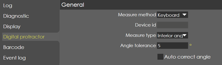
DigiProtractor

Device ID

Range

Assigned automatically

Default

Units

Access

Administrator

Function

Before setting up angle measuring device, it needs to be recognized by RA software. Steps to register an angle measuring device in RA :

  1. Click on the 'Select device' button in the Digital Protractor parameters page.

  2. Now device selection tab appears, now press the data button in the device.

  3. The input angle can be checked, and device ID is assigned automatically.

  4. Now close the machine parameter page and save changes made.

Description

Measure Type

Range

- / + interior or exterior angle

Default

- Interior angle

Units

Access

Administrator

Function

Measure Type determines the type of angle displayed in the protractor, whether it is interior or exterior angle and the direction of the angle measured.

Description

Angle tolerance

Range

Default

5

Units

Degree

Access

Administrator

Function

Angle tolerance is used when Auto correct angle is enabled. If the measure angle deviate from actual angle by more than angle tolerance, auto correct angle is disabled, and user need to apply the correction manually. Angle Input Sequence in RA :

  1. For smaller length bend length

    • Only central angle correction is available and angle from protractor is transferred to the central angle.

  2. If Auto correct angle is enabled, for each data transfer angle correction will be applied.

    • Otherwise, central angle will be overwritten.

  3. For longer bend length

    • Data transfer in run page will open angle correction page with three angles correction mode activated and all the angles will be populated with transferred angle.

    • Next data transfer will be entered in right end angle with central angle value equal to average of end angles.

    • Next data transfer will be entered in central angle.

  4. Mode is not changed automatically from central angle to end angle or from end angle to three.

For longer length program (length greater than Default → Bend cycle → Two / Three angle correction bend length limit), user should measure left angle first, then RightAngle Control and then central angle. After three measurement, angle correction will be applied automatically if the option is enabled. On each successful data transmission, mode will change from central angle, end angle and three angle correction.

Description

Auto correct angle

Range

checked / unchecked

Default

unchecked

Units

Access

Administrator

Function

Description

Contents

  • General
  • Device ID
  • Measure Type
  • Angle tolerance
  • Auto correct angle
Display Barcode

      Copyright © 2025 by TRUMPF SE + Co.KG. All rights reserved.

    Compiled by Bento