
Tools
General
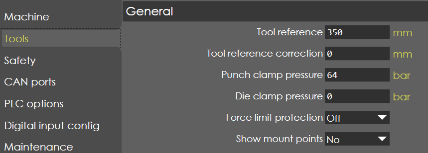
Tool reference
Range |
0-99999 |
Default |
350 |
Units |
mm |
Access |
Administrator |
Function
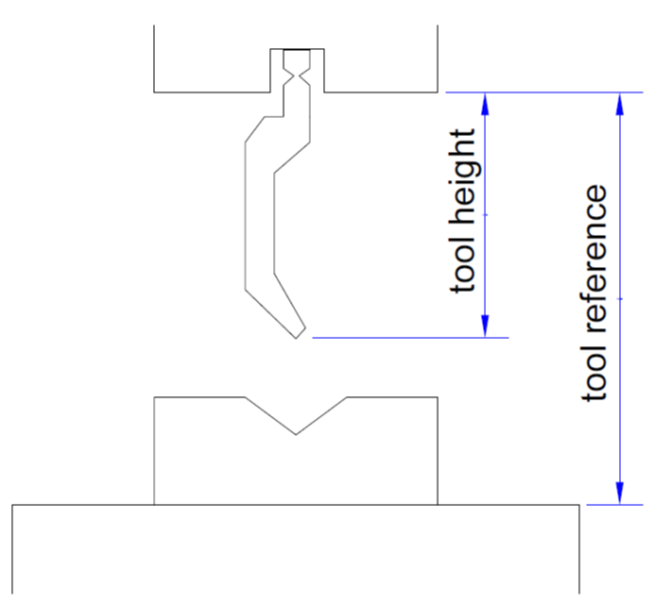
This parameter defines the distance between the upper RAM and bottom table called as 'Open Height' of the machine.
Description
Generally, the open height of the machine is referred to as the distance between the punch clamping surface and die sitting surface. This parameter is used for the calculation of bending depth, mute point and pinch point.
Tool reference correction
Range |
0-99999 |
Default |
0 |
Units |
mm |
Access |
Administrator |
Function
NA
Description
NA
Punch clamp pressure
Range |
1-1000 |
Default |
64 |
Units |
Bar |
Access |
Administrator |
Function
This parameter defines the pressure required to clamp the punch. It is used only when hydraulic clamping is provided for the punch. This parameter appears only when Punch clamp option is ON in PLC options under general parameters tab.
Description
In order to clamp the punch using hydraulic clamping, the required set pressure is programmed in this parameter and accordingly the main pressure valve output is controlled to give this required pressure for clamping.
Die clamp pressure
Range |
1-1000 |
Default |
64 |
Units |
Bar |
Access |
Administrator |
Function
This parameter defines the pressure required to clamp the punch. It is used only when hydraulic clamping is provided for the punch. This parameter appears only when Punch clamp option is ON in PLC options under general parameters tab.
Description
In order to clamp the punch using hydraulic clamping, the required set pressure is programmed in this parameter and accordingly the main pressure valve output is controlled to give this required pressure for clamping.
Force limit protection
Range |
ON/OFF |
Default |
OFF |
Units |
NA |
Access |
Administrator |
Function
This parameter activates the force limit protection during bending.
Description
During bending, the force generated due to tool resistance is compared with the programmed bending force, if the tool resistance force is too high, it automatically goes to decompression phase and then opening phase. After the completion of the bending cycle, an error message will appear on the screen.
Show mount points
Range |
Yes or No |
Default |
No |
Units |
NA |
Access |
Administrator |
Function
This parameter activates the LED indication of tool mounting points, if the LED option is available in the machine.
Description
To turn LEDs ON to show the mount points of the tools according to the backgauge position.
Clamping Options
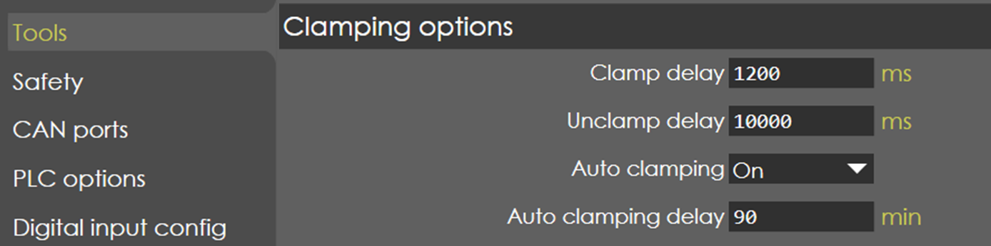
Clamp delay
Range |
0-60000 |
Default |
1200 |
Units |
ms |
Access |
Administrator |
Function
This is the delay till which the clamping digital input is ON after receiving the pressure feedback signal for clamping.
Description
This is done to make sure the clamping pressure stabilizes, and desired pressure reaches the clamping circuit from the clamping solenoid. This parameter appears only when clamp option is ON in PLC options under general parameters tab.
Unclamp delay
Range |
0-60000 |
Default |
1000 |
Units |
ms |
Access |
Administrator |
Function
This is the delay given for releasing the pressure from clamping circuit through the unclamping solenoid.
Description
This is done to make sure that pressure is released fully from the clamping circuit, if this delay is not given even after giving unclamping signal, the pressure will not be fully released, and tools cannot be removed.
Auto clamping
Range |
ON/OFF |
Default |
OFF |
Units |
NA |
Access |
Administrator |
Function
This must be ON if auto clamping function needs to be active.
Description
If this option is ON, auto clamping delay parameter appears. This is used to save time by automatically clamping the tools once in specified time period.
Auto clamping delay
Range |
0 to 60000 |
Default |
90 |
Units |
min |
Access |
Administrator |
Function
This defines the time period in which auto clamping occurs.
Description
For example, if auto clamping delay is 90 minutes, then auto clamping happens once in every 90 minutes automatically. This parameter appears only when auto clamping option is ON in clamping options in tools options under general parameters tab.
Safety
These safety parameters are related to RAM and backgauge axis with respect to punch and die.
Minimal intermediate X for Z distance
Range |
1-1000 |
Default |
10 |
Units |
mm |
Access |
Administrator |
Function
This parameter defines the minimum intermediate distance of X for Z-axes movement.
Description
If the backgauge lies within the die zone, then for any Z movement the backgauge retracts up to this set distance before moving Z axis. This is set in order to prevent the backgauge and die rubbing against each other.
Minimal intermediate R for X distance
Range |
1-1000 |
Default |
10 |
Units |
mm |
Access |
Administrator |
Function
This parameter defines the minimum intermediate distance of R for X-axes movement.
Description
If the R-axis position is lesser to this parameter distance, then first the X-axes is positioned to its target position, followed by R-axis. This make sure that the fingers are not collided directly to the tools.
If the backgauge lies within the die zone, then for any X movement the backgauge moves up for this set distance before moving X axis. This is set in order to prevent the backgauge and die rubbing against each other.
Safety X distance
Range |
0.1 to 50 |
Default |
40 |
Units |
mm |
Access |
Administrator |
Function
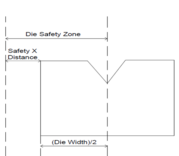
This parameter defines the die safety zone.
Description
This parameter is used to set the die safety zone. If set to zero, the safety zone is defined from centre of the die(zero) to (die width)/2 (from centre of the die to end of the die). For example, if die total width is 25 mm and this parameter is set to 0, then safety zone is set from 0 to 12.5 mm (die width/2). If this parameter is set to say 5 mm, then safety zone is set from 0 to 17.5 mm.
Consider reverse safety for X
Range |
Checked or unchecked |
Default |
Checked |
Units |
NA |
Access |
Administrator |
Function
This parameter is used to ignore minimal intermediate R for X distance when gauge is retracting (reverse X movement).
Description
This parameter is checked by default, so the minimal intermediate R for X distance is considered even for retraction movement (X axis away from tool).
This can be disabled by unchecking the check box in order to save time. If unchecked X retracts directly without considering minimal intermediate R for X distance even when backgauge is in safety zone.
Safety distance R below BG reference
Range |
0.1 to 1000 |
Default |
500 |
Units |
mm |
Access |
Administrator |
Function
Used to determine safety zone based on tool profile of die.
Description
Consider below die as example:
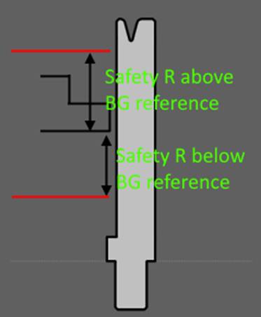
Total width of the die is 20 mm. But if we consider top region alone, the width is 16 mm. So, if the die is in Flipped state, the safety distance should be 6 mm and not 10 mm. It also depends on BG position. If BG safety zone is below the notch, the safety distance will increase from 6 mm to 10 mm. BG safety zone top is considered when dealing with punch. So, BG inside punch zone warning is raised based on whether the punch profile is inside the BG safety zone. If user give higher value like 500 mm, Safety zone is considered as bound of both die and punch.
Safety distance R above BG reference
Range |
0.1 to 1000 |
Default |
500 |
Units |
mm |
Access |
Administrator |
Function
Used to control display of BG inside punch zone warning message.
Description
Consider below die as example:
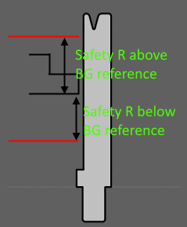
Total width of the die is 20 mm. But if we consider top region alone, the width is 16 mm. So, if the die is in Flipped state, the safety distance should be 6 mm and not 10 mm. It also depends on BG position. If BG safety zone is below the notch, the safety distance will increase from 6 mm to 10 mm. BG safety zone top is considered when dealing with punch. So, BG inside punch zone warning is raised based on whether the punch profile is inside the BG safety zone. If user give higher value like 500 mm, Safety zone is considered as bound of both die and punch.
Safety speed
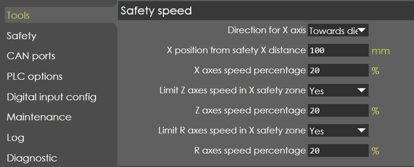
Direction for X axis
Range |
None/Towwards die |
Default |
Towwards die |
Units |
NA |
Access |
Function
Description
X position from safety X distance
Range |
0 to 1000 |
Default |
100 |
Units |
mm |
Access |
Function
Description
X axes speed percentage
Range |
0.1 to 100 |
Default |
20 |
Units |
% |
Access |
Function
Description
Limit Z axes speed in X safety zone
Range |
Yes/No |
Default |
Yes |
Units |
NA |
Access |
Function
Description
Z axes speed percentage
Range |
0.1 to 100 |
Default |
20 |
Units |
% |
Access |
Function
Description
Limit R axes speed in X safety zone
Range |
Yes/No |
Default |
Yes |
Units |
NA |
Access |
R axes speed percentage
Range |
0.1 to 100 |
Default |
20 |
Units |
% |
Access |
Function
Description
Display

Tool heights in run page
Range |
Checked/Unchecked |
Default |
Unchecked |
Units |
NA |
Access |
Function
Description
Safety X distance in run page
Range |
Checked/Unchecked |
Default |
Unchecked |
Units |
NA |
Access |
Function
Description
Min.limit for ton per meter overload
Range |
100 to 500 |
Default |
100 |
Units |
% |
Access |