
Machine
General

Service row
Range |
ON/OFF |
Default |
ON |
Units |
|
Access |
Administrator |
Function
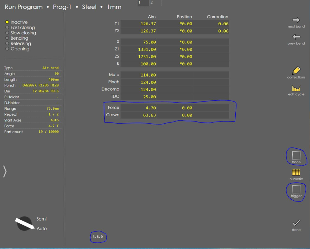
To display the complete status, Force & Crown dynamic values and trace functions related soft keys on the numeric screen of run page.
When ON is selected, the service row is available; when OFF is selected, the service row is unavailable.
Description
NA
Status display
In Service row, the status display is showed in numeric screen of run page at the Left side bottom as indicated in the picture. The status display 3.8.0 can be divided into three segments as follows:
-
Controller status
-
Machine status
-
Program run status
Controller status: The number and the corresponding meaning of status are as follows:
0 |
Controller is in Fatal error status and not recoverable until power restart. |
1 |
Controller is in Fatal error status and recoverable. |
2 |
Controller is in Normal error status and recoverable. |
3 |
Controller is in Ready status for operation. |
Machine Status: The number and the corresponding meaning of status are as follows:
0 - 7 |
The state from 0 to 8 displays the booting mode of the machine with defined parameters. |
8 |
Machine Booting process is completed. |
9 |
Backgauge axes are enabled. |
10 |
RAM and Backgauge axes are ready for operation. |
Program run Status: The number and the corresponding meaning of status are as follows:
0 |
Waiting for Start command (or) Axes are not referenced. |
1 - 3 |
Internal program functions. |
4 |
Wait for foot pedal close trigger. |
5 - 7 |
Internal parameter functions. |
8 |
Active motion of all axes until they reach their respective target positions. |
9 |
Dwell time. |
10 |
Internal function. |
11 |
Decompression start. |
12 |
Decompression end. |
Force & Crown values: In service row, additionally the Force and Crown, programmed & actual values are displayed in numeric screen of run page at the bottom of axis positions as marked in the picture.
Force values are displayed in units of tons and Crown values are displayed in units of micrometre (µm).
Trace related soft keys: In service row, trace and trigger soft keys are displayed in numeric screen of run page at the right side of other available soft keys as shown in the image below.
Machine name
Range |
NA |
Default |
NA |
Units |
NA |
Access |
NA |
Function
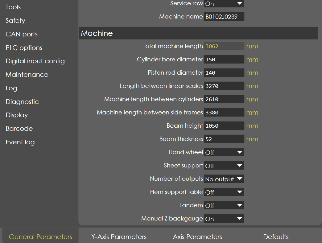
This parameter displays the name of the current machine.
Description
This parameter is not editable by the user as it is derived directly from the machine file with respect to machine ID.
Machine
Total machine length
Range |
NA |
Default |
NA |
Units |
mm |
Access |
Standard |
Function
This parameter displays the total length of the machine.
Description
This parameter is not editable by the user as it is derived directly from the machine file with respect to machine ID.
| When the operator programs a bending length longer than the total machine length a warning appears on the screen. |
Cylinder bore diameter
Range |
0-1000 |
Default |
150 |
Units |
mm |
Access |
Administrator |
Function
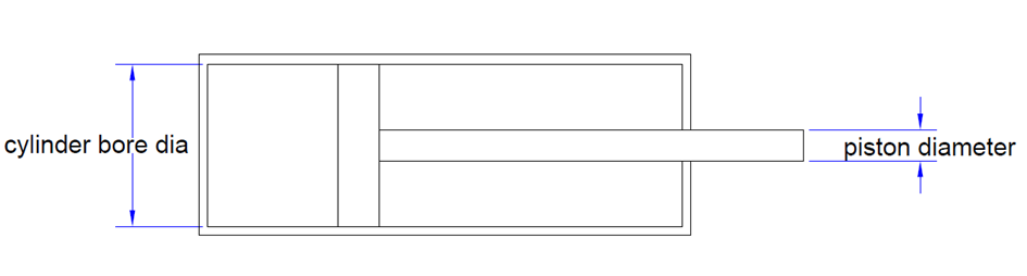
This parameter defines the bore diameter of the cylinder.
Description
This parameter defines the bore diameter of the cylinder.
Piston rod diameter
Range |
0-1000 |
Default |
140 |
Units |
mm |
Access |
Administrator |
Function
This parameter defines the diameter of the piston rod.
Description
This parameter defines the diameter of the piston rod.
Length between linear scales
Range |
0-99999 |
Default |
3270 |
Units |
mm |
Access |
Administrator |
Function
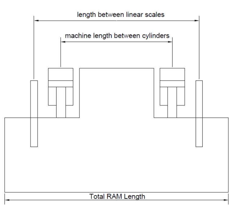
This parameter defines the distance between the left and right linear scales.
Description
The length between the left and right linear scales is used for the synchronization of tandem machine.
Machine length between cylinder
Range |
0-99999 |
Default |
2610 |
Units |
mm |
Access |
Administrator |
Function
This parameter defines the distance between the centre of left and right hydraulic cylinders.
Description
The length of machine table between the centre of left and right cylinders is used to compute the table deflection.
Machine length between side frame
Range |
0-99999 |
Default |
3380 |
Units |
mm |
Access |
Administrator |
Function
This parameter defines the distance between the two side frames of the machine.
Description
The length between the left and right-side frames is used for crowning computation, if the hydraulic crowning is enabled in the machine.
Beam height
Range |
0-99999 |
Default |
1050 |
Units |
mm |
Access |
Administrator |
Function
This parameter defines the height of the upper beam (RAM).
Description
The height of the RAM is used for the internal computation to calculate the rigidity factor of the beam.
Beam thickness
Range |
0-99999 |
Default |
52 |
Units |
mm |
Access |
Administrator |
Function
This parameter defines the thickness of the upper beam (RAM).
Description
The thickness of the RAM is used for the internal computation to calculate the rigidity factor of the beam.
Inertia under beam
Range |
0-99999 |
Default |
1238 |
Units |
mm |
Access |
Administrator |
Function
This parameter defines the centre moment of inertia of the under beam called machine table.
Description
The moment of inertia of the machine table is used to compute the table deflection according to the amount of force acting on it.
Inertia upper beam
Range |
0-99999 |
Default |
1100 |
Units |
NA |
Access |
Administrator |
Function
This parameter defines the centre moment of inertia of the upper beam called RAM.
Description
The moment of inertia of the RAM is used to compute the beam deflection according to the amount of force acting on it.
Relaxation stiffness
Range |
1-1000 |
Default |
4 |
Units |
µm/KN |
Access |
Administrator |
Function
This parameter defines the relaxation stiffness of the frame.
Description
The relaxation stiffness parameter is used to compute the decompression distance. Generally, this value multiplied with computed force is the decompression distance. It is also used in deflection computation if linear is selected in deflection method (Machine settings → Defaults → Bend Program → deflection method).
Stiffness of frame
Range |
1-100 |
Default |
80 |
Units |
% |
Access |
Administrator |
Function
This parameter defines the stiffness of the frame used to compute the Y-axis depth calculation.
Description
The stiffness of frame is used to compute the deflection of the side frame according to the programmed force. Thereby the compensation distance due to deflection of side frame is adjusted in Y-axis depth calculation.
This parameter is programmed as a percentage of the value programmed for the machine parameter 'Relaxation Stiffness'.
Hand wheel
Range |
ON/OFF |
Default |
OFF |
Units |
NA |
Access |
Administrator |
Function
This parameter enables the handwheel function in the machine.
Description
Using handwheel, RAM (Y-Axis) and all the backgauge axes are moved in a very precise manner. It is mainly used during manual clamping of tools, where the pressure is set to minimum, the punch and die brought in contact with each other and then clamped to make sure the centre between the tools are aligned.
Sheet Support
Range |
ON/OFF |
Default |
OFF |
Units |
NA |
Access |
Administrator |
Function
This parameter enables the sheet follower function in the machine. Only if this parameter is ON the S1 and S2 axis settings will be displayed.
Description
Sheet support is used to support the part and reducing human effort and increasing bend accuracy. Kindly note that to use sheet support function, sheet follower license needs to be enabled in license feature list.
Sheet support implementation is as follows:
-
S1 and S2 will be move to 0 when back gauge is positioned irrespective of whether bend required sheet support to move. This is to ensure sheet support is in flat condition when bending a part.
-
If the sheet support is enabled corresponding S1 or S2 or both will move while bending.
-
After reaching TDC, S1 or S2 or both will return to flat position if it is enabled.
Axis parameter for S1 and S2 are similar to other axis except for minor changes like the minimum and maximum unit is degrees.
Manual Z backgauge
Range |
ON/OFF |
Default |
OFF |
Units |
NA |
Access |
Service |
Function
Manual Z backgauge control allows the operator to adjust and position the backgauge along the Z-axis for precise sheet metal bending. This setting will inform the user whether there is a provision to mount an extra Z-axis back gauge in the machine
Description
Enables manual input for side-to-side backgauge positioning, ensuring accurate placement of the workpiece.