
Crowning
Configuration
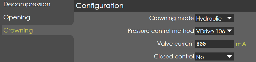
Crowning mode
Range |
None / Hydraulic / Motorized |
Default |
Hydraulic |
Units |
NA |
Access |
Administrator |
Function
This parameter defines the type of crowning used in the machine.
Description
The control supports two types of crowning called Hydraulic and Motorized types. This parameter selects the type of the crowning used.
Pressure control method
Range |
VDrive 106 / External |
Default |
VDrive 106 |
Units |
NA |
Access |
Administrator |
Function
This parameter defines the hydraulic pressure control method used in the machine.
Description
This parameter is used to select whether VDrive 106 or an external amplifier is used to control crowning pressure.
Valve current
Range |
0-3000 |
Default |
800 |
Units |
mA |
Access |
Administrator |
Function
This parameter defines the maximum current of Crowning Valve.
Description
The control can support a maximum of 3 amps valve current and this parameter defines the actual current of the valve used in the machine. In this way, it is possible to use the maximum output voltage of the controller for the better resolution of crowning distance.
| This parameter is only valid, if the Crowning mode is Hydraulic and Pressure control method is VDrive 106. If Pressure control method is set to External, Valve current is not available. |
Closed control
Range |
Yes / No |
Default |
No |
Units |
NA |
Access |
Function
Description
This parameter is applicable only when Crowning mode is set to Hydraulic.
General
Minimum
Range |
0-1000 |
Default |
0 |
Units |
µm |
Access |
Administrator |
Function
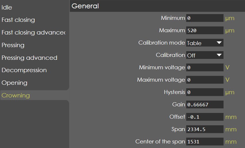
This parameter defines the minimal value of crowning distance.
Description
If the computed crowning value is less than this parameter, then the crowning distance is taken from this parameter. Also, this minimal value is used for the interpolation of crowning distance, if the calibration mode is selected as linear.
Maximum
Range |
0-3000 |
Default |
520 |
Units |
µm |
Access |
Administrator |
Function
This parameter defines the maximum value of crowning distance.
Description
If the computed crowning value is greater than this parameter, then the crowning distance is taken from this parameter. Also, this maximum value is used for the interpolation of crowning distance, if the calibration mode is selected as linear.
Calibration mode
Range |
Linear / Table |
Default |
Table |
Units |
|
Access |
Administrator |
Function
This parameter defines the type of calibration activated in the machine.
Description
The control supports two types of calibration method, 1. Linear, 2. Table. When linear is selected, with the help of minimum and maximum value the other values are interpolated internally. When table is selected, the control voltage versus crowning distance are entered in a table.
Calibration
Range |
ON/OFF |
Default |
OFF |
Units |
|
Access |
Administrator |
Function
This parameter enables/disables the calibration of crowning distance.
Description
This parameter must be ON, if required to calibrate the crowning distance. The calibration of the crowning is done by defining the relation between the controller voltage command (Range: 0 to 10V) and the crowning distance (µm) which is programmed in a table. For calibration to be ON, valve calibration must be OFF in pressure valve tab in Y-axis parameter.
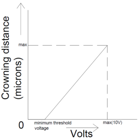
The relation between the crowning distance and voltage can be entered in a table by pressing the calibrate softkey available in the page.
| Crowning calibration ON option will be available only when pressure Calibration is set to OFF in Y-Axis Parameters → Pressure valve → General. |
Calibration procedure
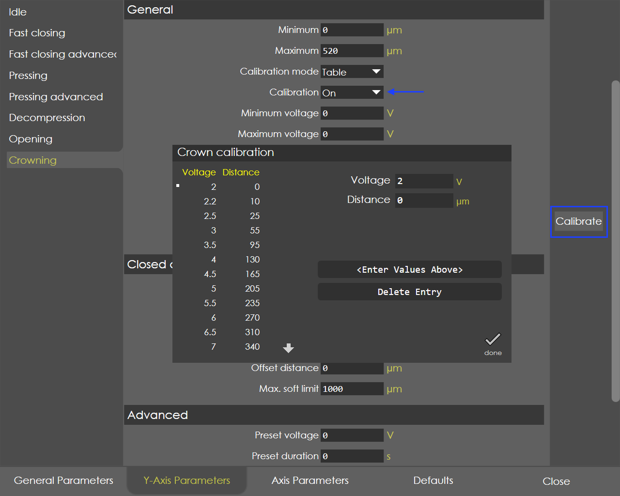
Set the calibration parameter to ON and save it.
| Access level must be service. |
-
Go to the same page, you can find the softkey "Calibrate".
-
Press the calibrate button, a new page called "Crown calibration" will appear on the screen.
-
Default voltage calibration step is 1.0 V and total number of points is 11. The calibration step, no. of points can be changed using the soft key "Delete Entry", "Add Entry".
-
The display "Voltage" shows the active voltage command and the corresponding crowning distance (measured by dial gauge or other means) to be entered in the box "Distance in µm".
| When the Pump servo control is used, and crowning type is hydraulic during calibration the speed of the pump needs to be maintained constant and it depends on the type of the machine and the pump. So, servo speed is displayed in the crowning calibration page. |
-
The controller accepts the active voltage command only after pressing the foot pedal open switch, to ensure the safety.
-
After entering the crowning distance, press the soft key "Update Entry", it will update the table with respective display values of voltage and distance.
Minimum voltage
Range |
0-10 |
Default |
0 |
Units |
V |
Access |
Administrator |
Function
This parameter defines the minimum threshold voltage of crowning.
Description
This parameter is valid only if the crowning mode is selected as "Linear". This is the minimum threshold voltage below which the change in voltage doesn’t affect the crowning distance. This voltage is very important to calculate the interpolation voltage for the computed crowning distance. For instance, in hydraulic crowning, below 2 V there is no change in crowning distance and hence the minimum threshold voltage is 2V.
Maximum voltage
Range |
0-10 |
Default |
0 |
Units |
V |
Access |
Administrator |
Function
This parameter defines the maximum voltage of crowning.
Description
This parameter is valid only if the crowning mode is selected as "Linear". This is the maximum voltage that the control can output, by this way the maximum crowning distance can be limited. This voltage is very important to calculate the interpolation voltage for the computed crowning distance.
Hysteresis
Range |
1-10000 |
Default |
0 |
Units |
µm |
Access |
Administrator |
Function
This parameter defines the switch-off point for the programmed voltage.
Description
This parameter is valid only if the crowning mode is selected as “Motorized”. Because of the inertia of the crowning device, a hysteresis might be necessary to compare the command & actual crowning voltage and stop the crowning device at the correct position.
Gain
Range |
0.001 to 1 |
Default |
0.66667 |
Units |
NA |
Access |
Administrator |
Function
This parameter defines the gain factor for the computation of Crowning values.
Description
The gain factor can be tuned to get the better value for crowning .Thereby the OEM’s has the control over the crowning deflection depending on the type of crowning used in the machines.
Offset
Range |
-5 to 5 |
Default |
-0.1 |
Units |
NA |
Access |
Administrator |
Function
This parameter defines the effect of crowning in the lower bed; accordingly, the Y1 & Y2 axis positions are computed.
Description
This offset defines the effect of crowning in the lower bed with respect to the centre of the machine. If the crowning is offset by this parameter distance, then accordingly the Y1 & Y2 axis positions are computed.
Span
Range |
-9999 to 9999 |
Default |
2334.5 |
Units |
mm |
Access |
Administrator |
Function
This parameter defines the length of the crowning effect.
Description
Depends on the type of crowning, the span of crowning effect may be different. With this parameter, the crowning effect length is used to compute the Y1 & Y2 axis positions.
Centre of span
Range |
-9999 to 9999 |
Default |
1531 |
Units |
mm |
Access |
Administrator |
Function
This parameter defines the centre of crowning effect, where it will be maximum.
Description
NA
Advanced

This parameter is available only when Crowning mode is set to Hydraulic.
Preset voltage
Range |
0 to 10 |
Default |
0 |
Units |
V |
Access |
Administrator |
Function
Description
Preset duration
Range |
0 to 100 |
Default |
0 |
Units |
Sec |
Access |
Administrator |
Function
Description
Homing

Position
Range |
0 to 100 |
Default |
0 |
Units |
Sec |
Access |
Administrator |
Function
Description
Wait time
Range |
0 to 100 |
Default |
0 |
Units |
ms |
Access |
Administrator |
Function
Description
Reset time
Range |
0 to 100 |
Default |
300 |
Units |
ms |
Access |
Administrator |