
Pressing
Speed and acceleration
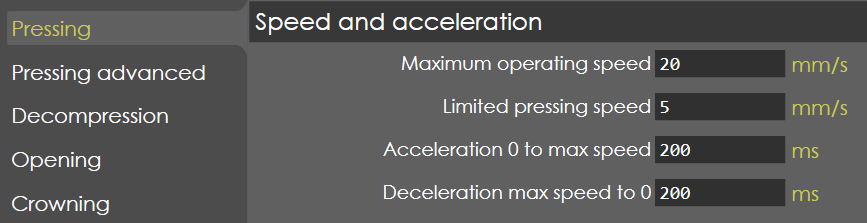
Maximum operating speed
Range |
0-25 |
Default |
10 |
Units |
mm/s |
Access |
Administrator |
Function
This parameter defines the maximum travel speed of the Y-axis during pressing.
Description
Normally this value should be programmed to the maximum possible speed of the axis, when the control signal is at maximum.
Limited pressing speed
Range |
0-30 |
Default |
10 |
Units |
mm/s |
Access |
Administrator |
Function
This parameter is not validated.
Description
NA
Acceleration 0 to max speed
Range |
0-2000 |
Default |
200 |
Units |
ms |
Access |
Administrator |
Function
This parameter defines the acceleration time of Y-axis during pressing.
Description
This is the nominal acceleration of the axis, used to control the axis from zero to maximum speed in the pressing phase. This parameter must be programmed as the time in which the axis accelerates from zero to maximum speed.
Deceleration max speed to 0
Range |
0-2000 |
Default |
200 |
Units |
ms |
Access |
Administrator |
Function
This parameter defines the deceleration time of Y-axis during pressing.
Description
This is the nominal deceleration of the axis, used to control the axis from maximum to zero speed when axis comes to its position in the pressing phase. This parameter must be programmed as the time in which the axis decelerates from maximum to zero speed.
Gain
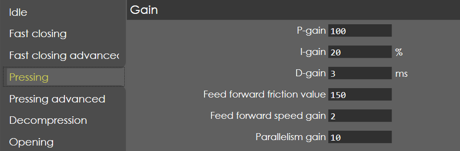
P-gain
Range |
0.1-999.99 |
Default |
200 |
Units |
NA |
Access |
Administrator |
Function
This parameter defines the Proportional gain factor of Y-axis during pressing phase.
Description
This gain factor defines the response to changes in the control signal. A high gain gives a quick response, if the gain is too high it will cause oscillation.
I-gain
Range |
0-999.99 |
Default |
30 |
Units |
% |
Access |
Administrator |
Function
This parameter defines the integral gain factor for the Y-axis during pressing phase.
Description
The integral gain is used for accurate positioning of the axis.
D-gain
Range |
0-2000 |
Default |
0 |
Units |
ms |
Access |
Service |
Precondition
The D-gain option will only be available when:
The External amplifier type is set to EV2D (Y-Axis Parameters > General > External amplifier type).
The Pressure control type is set to Proportional valve (Y-Axis Parameters > Pressure valve > Pressure control type).
Function
This parameter defines the derivative gain factor for the ram axis during the pressing phase.
Description
The derivative gain is used to minimize oscillations and ensure smooth, stable movement of the ram axis by adjusting the response based on the rate of change of the position.
Feed forward friction value
Range |
0-999.9 |
Default |
100 |
Units |
NA |
Access |
Service |
Function
This parameter defines the gain factor for braking of Y-axis during closing phase.
Description
To set gain factor for the axis when approaching the programmed position for a quick and smooth approach to mute point.
Feed forward speed gain
Range |
0-999.9 |
Default |
150 |
Units |
NA |
Access |
Service |
Function
This parameter defines the gain factor for braking of Y-axis during pressing phase.
Description
To set the gain factor for the axis when approaching the programmed position for a quick and smooth approach to the bend position.
Parallelism gain
Range |
1-1000 |
Default |
10 |
Units |
NA |
Access |
Administrator |
Function
This parameter defines the gain factor for parallelism control of Y-axis during fast closing.
Description
The parallelism during pressing can be adjusted with this parameter. A higher value will result in a smaller difference between Y1 and Y2 during the movement. In practice this difference should be approximately 0.01 - 0.03 mm.
| Programming this value too high will result in unstable movement of the beam. |
General
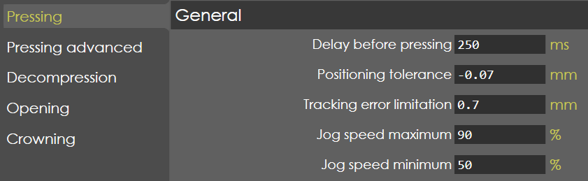
Delay before closing
Range |
0-2000 |
Default |
250 |
Units |
ms |
Access |
Administrator |
Function
This parameter defines the time needed to close the height retaining valves and suction valves.
Description
When the pressing command becomes active, the proportional valves will not be opened until this delay time has elapsed, to make sure the synchronized start of beam speed after the closing of height retaining and suction valves on either side.
Positioning tolerance
Range |
-9.999 to -0.005 |
Default |
-0.07 |
Units |
mm |
Access |
Administrator |
Function
This parameter defines the positioning tolerance for the Lower Dead Point (LDP) output.
Description
When the Y-axis reaches the bending position, the LDP output becomes high. With this parameter the tolerance is programmed when the LDP output may become active.
Tracking error limitation
Range |
0-100 |
Default |
0.7 |
Units |
mm |
Access |
Administrator |
Function
This parameter defines the maximum allowed difference between the computed position and actual position, during pressing phase.
Description
The controller will try to match the commanded and actual position as accurate as possible. The tracking error also called as lag error, is the difference between the commanded and actual position. The limitation here is the maximum tracking error allowed during pressing.
Jog speed maximum
Range |
1-100 |
Default |
9 |
Units |
% |
Access |
Administrator |
Function
This parameter defines the maximum speed in jog or manual mode.
Description
This parameter is defined in terms of percentage with reference to the maximum speed of pressing. Also, this speed corresponds to the big plus and minus button available in jog mode page.
Jog speed minimum
Range |
1-100 |
Default |
50 |
Units |
% |
Access |
Administrator |
Function
This parameter defines the minimum speed in jog or manual mode.
Description
This parameter is defined in terms of percentage with reference to the maximum speed of pressing. Also, this speed corresponds to the small plus and minus button available in jog mode page.